What is aluminium anodising?
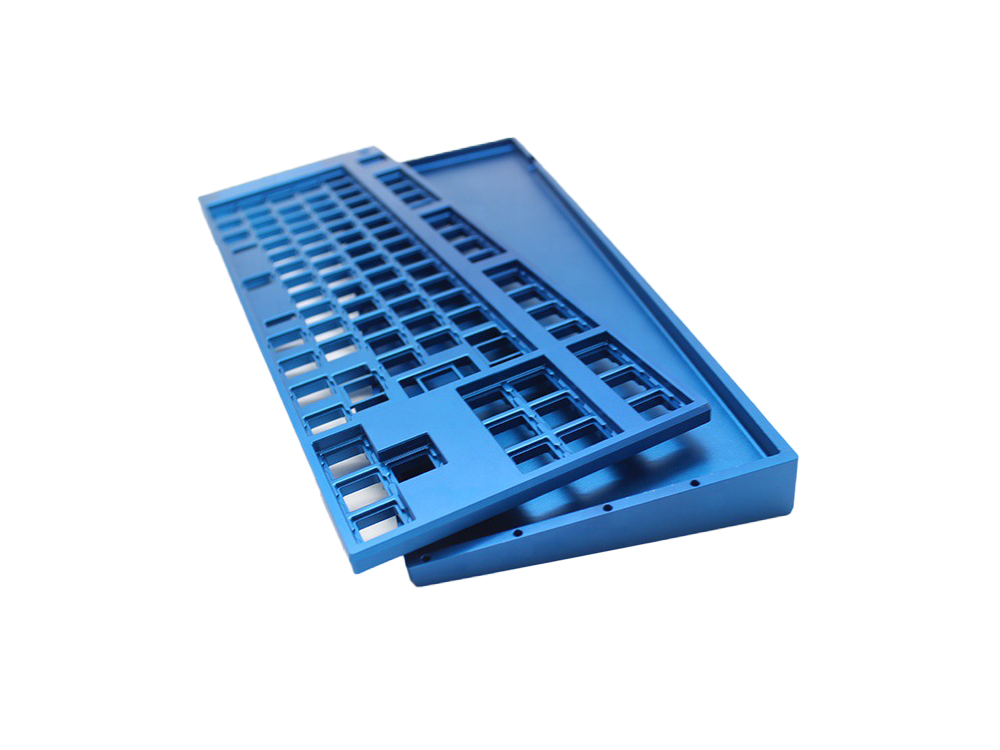
Anodising is an electrochemical conversion of the aluminium surface into an oxide layer. The coating can be natural or dyed, with alloy, pretreatment and sealing influencing the result. Conventional anodising and hard anodising serve different functions and should be specified separately.
Key specifications
Process references and example callouts are identified below. CHIHENG confirms the accepted material, dimensions and treatment requirements in the part quotation.
| Parameter | Reference / what to specify |
|---|---|
| Materials | Aluminium; state the alloy and temper, for example 6061-T6 or 6063-T6. |
| Thickness reference | Conventional dyed: 5–25 µm; common hard-anodising guidance: 40–60 µm. Industry references, not a CHIHENG acceptance range. |
| Tolerance | Specify final dimensions after treatment; identify threads, fitted bores and contact faces. |
| Colour | Natural, black or specified dye/sample reference; alloy affects colour matching. |
| Specification | ISO 7599 for decorative/protective anodising; ISO 10074 for hard anodic coatings. State the contract edition. |
| Part size | Review rack position, electrical contact, immersion envelope and geometry from CAD. |
Technical references: Anodising thickness guidance · TIGER Series 68 technical guidance · ISO 7599:2018 · ISO 10074:2021
Applications
Electronics
Aluminium housings and front panels with a specified colour.
Automation
Machined brackets and covers with defined surface protection.
Mechanical assemblies
Wear components where a hard-anodising specification is appropriate.
Working with CHIHENG
A direct conversation with our team, from your first drawing to delivery.
A reply within 24 hours
Send us your drawing and questions. Our team will reply within 24 hours and help you work out the next step.
An experienced engineering team
Talk through materials, tolerances and finishing with engineers who understand how your part will be made.
Machining equipment
We use our machining equipment and practical manufacturing experience to turn your drawings into finished parts.
Competitive worldwide shipping
We offer competitive shipping solutions for customers around the world, with options to suit your destination and delivery schedule.
Process steps
- Confirm alloy, coating type, thickness, colour, sealing and masked areas.
- Prepare and rack the component with agreed electrical contact locations.
- Form the oxide coating, then colour and seal as specified.
- Inspect the required thickness, appearance and final functional dimensions.
Aluminium anodising vs Powder Coating
| Comparison point | Aluminium anodising | Powder Coating |
|---|---|---|
| Substrate | Primarily aluminium in this service | Suitable metal substrates with appropriate pretreatment |
| Appearance | Metallic appearance influenced by alloy | Opaque colour and texture from the powder system |
| Thickness reference | Conventional dyed anodising: 5–25 µm | TIGER Series 68 smooth-finish example: 60–80 µm |
| Fit / contact | Oxide growth affects fits; contact faces need review | Deposited film adds build on threads and mating surfaces |
Planning an anodised part
- Mark the fits and dimensions that matter after anodising, along with the coating thickness.
- Share the alloy, colour and a sample if appearance needs to match another part. Different alloys and welds can look different after treatment.
- Show where rack marks are acceptable and which contact surfaces should remain uncoated.
FAQ
Can all aluminium alloys look the same after anodising?
Aluminium alloy, temper and surface preparation influence the appearance after anodising. Parts made from different alloys may not match even when the same dye is used. Identify the grade and cosmetic faces, then agree a representative sample and acceptable variation for the complete finished assembly before treating a production batch.
Does a colour reference define the complete finish?
A colour reference does not define the coating type, thickness, sealing or final dimensional condition. Include those requirements with the colour and visible-face reference on the drawing. For appearance-critical parts, agree the sample and permitted variation separately from the functional coating requirements so both aspects have a clear acceptance basis.
Should threads and fitted bores be masked?
Mark bores, threads, sealing surfaces and electrical contact areas requiring protection, and specify final dimensions after treatment. Oxide formation changes the finished surface, so machining allowance and masking should be reviewed together. The quotation should identify the accepted coating and inspection scope for those interfaces rather than assuming they remain unchanged.
Which anodising thickness should I specify?
Choose the thickness from the intended function and coating standard. Published finisher guidance gives 5–25 µm for conventional dyed anodising and 40–60 µm for many hard-anodising applications. These reference ranges are not universal acceptance limits. Put the required range, coating type, sealing and verification requirements on the drawing.
How is hard anodising different from conventional anodising?
Hard anodising is normally selected for functional wear requirements, while conventional anodising is commonly selected for appearance and general surface protection. Hard coatings can be darker and more alloy-dependent. A thicker coating is not automatically preferable: define the final fit, intended function, sealing and acceptance tests before choosing the process.